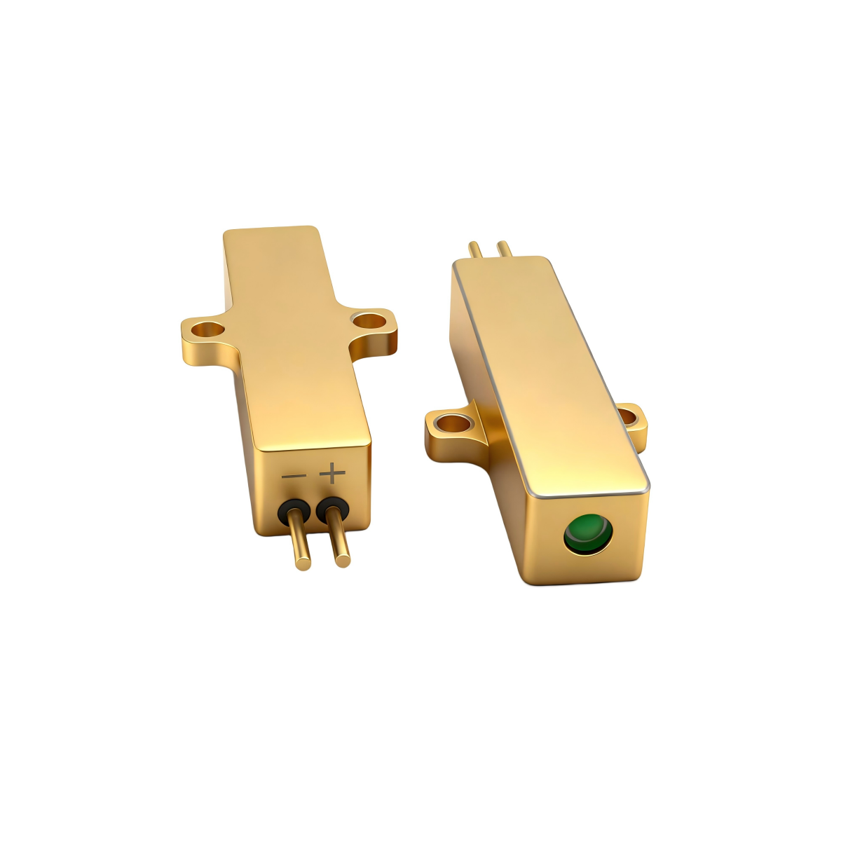


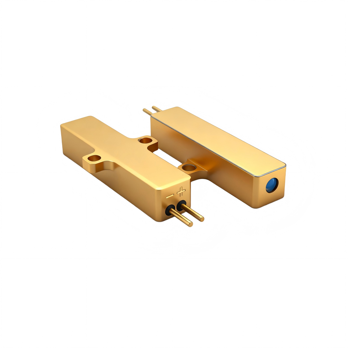


ER500 1535nm 500µJ Eye-Safe Laser for Long-Range LiDAR and Rangefinders
PRODUCT OVERVIEW
ER500 is a compact 1535 nm pulsed laser source based on Er:Yb glass microchip technology, designed for long-range LiDAR and rangefinders.
KEY FEATURES
- ✔ 1535 nm Eye-Safe Operation (Class 1)
- ✔ 500µJ Pulse Energy
- ✔ Compact OEM Design
- ✔ High Pulse Stability
- ✔ Long Lifetime
TECHNICAL SPECIFICATIONS
| Wavelength | 1535 nm |
| Pulse Energy | ≥500 µJ |
| Pulse Width | 6 ns |
| Beam Quality | TEM00 |
| Operation | Pulsed |
| Lifetime | ≥1 million shots |
| Drive pulse width | ≤2.4 ms |
| Pulse repetition rate | 1~10Hz |
| Pulse stability | 10% |
| Raw Beam Diameter | 0 .3 mm |
| Beam divergence angle | ≤ 7 mrad |
| Operating temperature | -40 ℃ ~ +65 ℃ |
| Storage temperature | -55 ℃ ~+ 75℃ |
| Dimension (mm) | 35×8×6.8mm3 |
| Weight | 12 g |
| Voltage | 2 V |
| Electric current | 20 A |
| Shock | 1500 G, 0.5 ms |
| Vibration | 20~2000 Hz/20 G |
APPLICATIONS


DOWNLOADS
- Datasheet (PDF)
- 3D model — rotate it on this page, or download the GLB
- Outline drawing (STEP) — request from our team
- Integration guide — request from our team
Product Description
ER500 1.54µm / 1535nm 500µJ Eye-Safe Erbium Glass Microchip DPSS Laser
The ER500 is a high-energy 1535nm eye-safe erbium glass microchip DPSS laser designed as a transmitter core for long-range LiDAR, laser rangefinders and target-designation modules. It combines a diode-pumped Er³⁺:glass gain medium with a compact microchip cavity, delivering nanosecond pulses in a slim board-level package that is easy to integrate into airborne, vehicle and handheld systems.
The laser provides single-pulse energy of at least 500µJ with a typical pulse width of 6ns and a pulse repetition rate adjustable from 1 to 10Hz. Pulse stability is specified at 10%. The raw beam diameter is about 0.3mm, with divergence ≤ 7mrad and TEM₀₀ beam mode, giving a tight, near-Gaussian beam that is straightforward to collimate for multi-kilometer outdoor ranging.
Mechanically, the ER500 is housed in a 35×8×6.8mm³ package and weighs around 12g, making it suitable for direct mounting on driver PCBs where space and mass are at a premium. It is driven from a low-voltage, high-current pulse: typical load voltage is about 2V, operating current is 20A, drive pulse width ≤ 2.4ms and repetition rate up to 10Hz. The driver power supply must match these parameters; if not, the laser may fail to start properly or could be overloaded and permanently damaged.
The ER500 is designed for harsh environmental conditions. The operating temperature range is −40°C to +65°C and the storage range is −55°C to +75°C. Shock resistance is rated at 1500G for 0.5ms, and vibration tolerance is 20–2000Hz at 20G. Lifetime is specified at more than 1 million shots, aligning with the requirements of long-life fielded LiDAR and rangefinding platforms.
Operation guidelines emphasize safe wiring and correct parameter setup. Power must be fully disconnected before making connections; polarity must be checked carefully, and all terminals must be firmly tightened to avoid short circuits, reverse polarity and intermittent contacts. After wiring, parameters on the driver should be set strictly according to the factory test report before enabling emission, ensuring that voltage, current, pulse width and repetition rate stay within the specified range. The output window must be kept clean and should not be touched; if contamination occurs, it should be cleaned before operation. When mounting the device via the side lugs, a torque of about 0.2 N·m is recommended to maintain mechanical stability without distorting the housing.
With its 1.54µm wavelength, the ER500 operates in an eye-safer band where radiation is strongly absorbed by the cornea and lens instead of directly reaching the retina. This, combined with low atmospheric attenuation and good penetration in haze, rain and aerosol, makes the ER500 especially suitable for open, man-in-the-loop applications. Typical scenarios include long-range laser rangefinders, UAV and airborne LiDAR payloads, compact EO/IR gimbals, ship-borne and vehicle-mounted sensor heads, as well as industrial mapping, structural monitoring and robotic perception systems that require multi-kilometer performance with an eye-safe source.
OUTLINE DIMENSION

Figure 1 Outline Dimensions(mm)
Operating Instructions
- Match the laser driver to the ER500 laser.
The laser driver power supply must be properly matched to the laser.
The typical load voltage of the ER500is < 2 V, with an operating current of 20 A, pulse width < 2 ms, and a repetition rate of 10 Hz. For the exact operating parameters, please refer to the attached factory test report. The laser driver power supply must meet these requirements; otherwise, the laser may fail to operate properly or could be overloaded and permanently damaged. Therefore, before wiring, carefully check the laser specification sheet and confirm that the laser is compatible with the selected driver. - Always disconnect power before wiring.
Before making any connections, make sure the power is switched off and completely isolated. During wiring, carefully check the positive and negative terminals of the laser and ensure correct polarity. After the wiring is completed, perform a thorough inspection to confirm that all connections are correct, in order to avoid short circuits, reverse polarity, and other faults. At the same time, make sure all terminals are firmly secured to prevent poor contact due to loose wiring. - Set operating parameters according to the factory test report.
After confirming that the wiring is correct, set the corresponding parameters on the driver according to the attached factory test report. Once the parameters are correctly set, turn on the driver; the laser should then operate normally. - Keep the laser output window clean.
Take care to keep the laser output window clean and do not touch the window surface. If contamination occurs, clean the window thoroughly beforeoperating the laser. - Use the correct mounting torque.
Because the overall length of the laser housing is relatively long, when fastening the laser via the mounting lugs on both sides, use a torque screwdriver set to 2 N·m. Excessive or insufficient torque may affect the mechanical stability and performance of the laser.
Interactive 3D Model
Drag to rotate, scroll to zoom. The controlled STEP source is available on request for design release.
ER500